Warner Electric Actuator Wiring Diagram

Rh 0405 Way Switch Wiring Diagram On Electric Linear Actuator Wiring Diagram Schematic Wiring
3bfad4 Electric Linear Actuator Wiring Diagram Wiring Library

Thomson Linear K2p1 0g10 12v Br 12 Actuator B Track 12 Vdc 600 Lbf Connector Special Mrosupply Com

How To Wire A Rocker Switch To Linear Actuator

Solved Need Wiring Diagram For The Borg Warner 4405 Control Trac Fixya
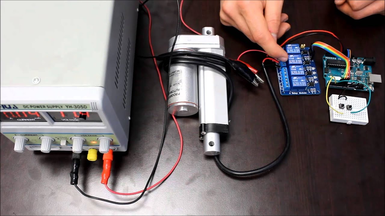
How To Use Relays To Control Linear Actuators Youtube

A wiring diagram is a simplified standard photographic representation of an electric circuit.
Warner electric actuator wiring diagram.

Yx 4003 Wiring Diagram Auma Motorised Valve Wiring Diagram Motorised Valve Schematic Wiring
Abz Electric Actuator Wiring Diagram Linear Actuator Wiring Diagram Free Wiring Diagram Abz Pneumatic And Electric Actuators Valve Automation Limitorque L120 Wiring Diagram Collection Wiring Collection Warner Linear Actuator Wiring Diagram Free
External Limit Switch Kit For Actuators In 2020 Linear Actuator Actuator Switch

Diagram Borg Warner Actuator Wiring Diagram Full Version Hd Quality Wiring Diagram 1cabinetwiring1 Mairiedebonnat Fr

Zl 7420 Borg Warner Gauge Wiring Diagram Wiring Diagram

Stewart Warner Stewart Warner 3 3 8 In Wings Electric Diesel Tachometer 3 500 Rpm 82672 82672

Synchronous Control Of Two Optical Linear Actuators Using An Arduino Linear Actuator Arduino Actuator

How To Adjust Limit Switches On Heavy Duty Linear Actuator Progressive Automations Youtube

External Limit Switch Kit For Actuators Linear Actuator Actuator Switches

Gx 7338 Van De Graaff Generator Diagram Http Wwwpic2flycom Vandegraaff Free Diagram

Single Phase Wiring Diagram For House Bookingritzcarlton Info Electrical Circuit Diagram Circuit Diagram Capacitors

Diagram Time Warner Wiring Diagrams Full Version Hd Quality Wiring Diagrams Humanbraindiagrams Blidetoine Fr

Warner Linear H Track Electric Actuator Youtube

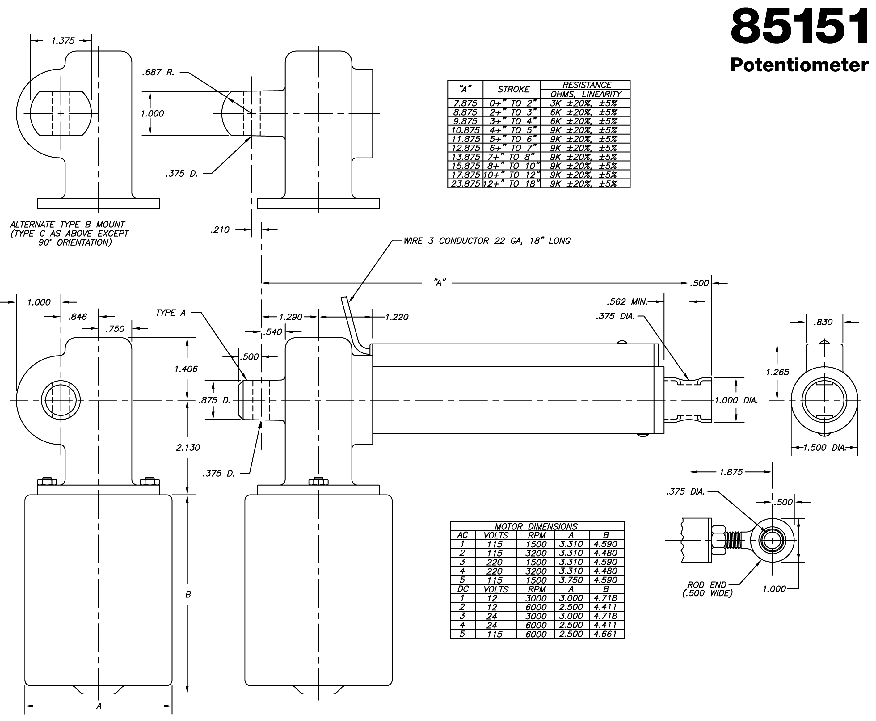
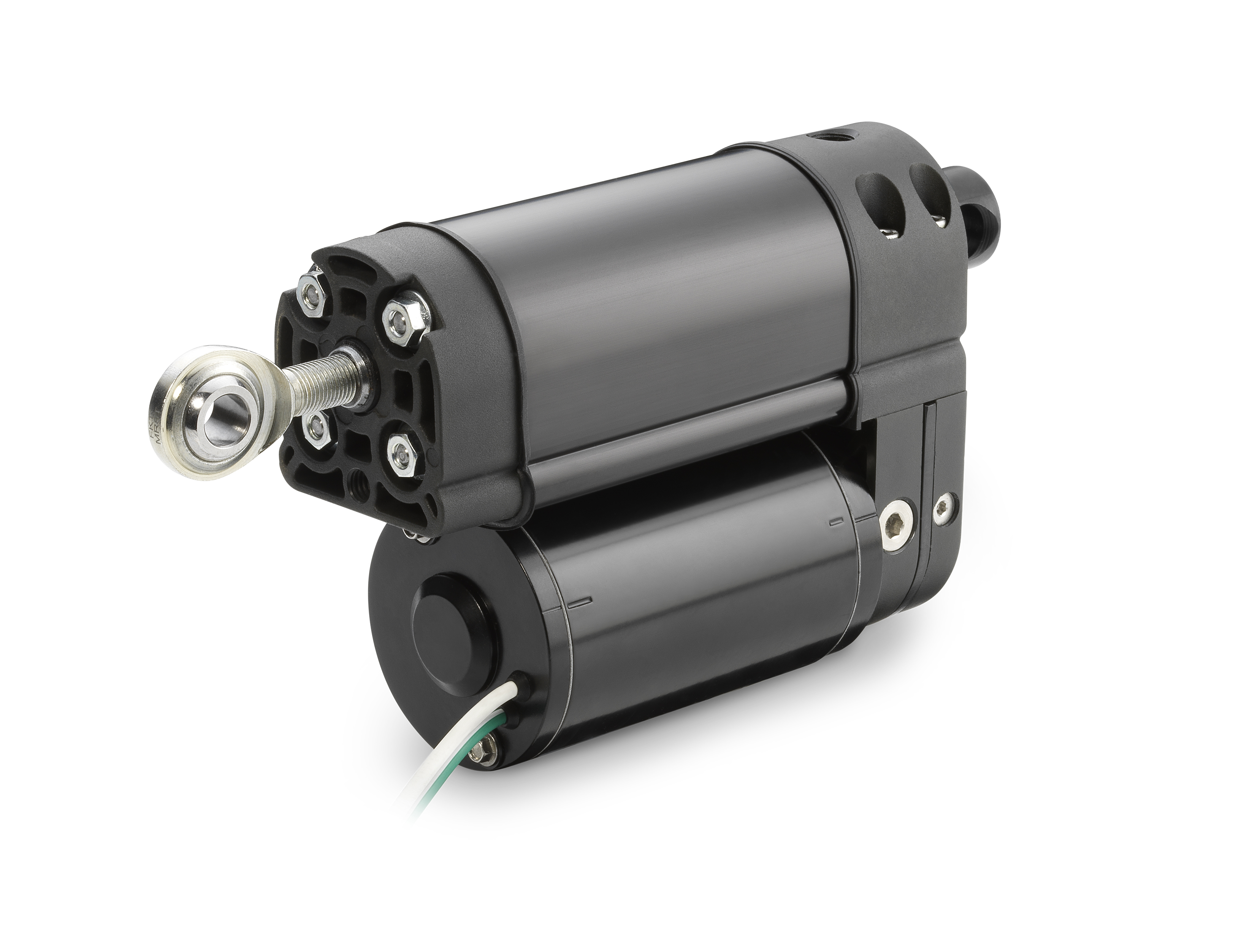
Warner Electric Linear Actuator P N S12 17a8 06 25320 Flying Fish Aircraft Parts

Diy Reciprocating Cycle Linear Actuator Motor Electric Motor Gear Box 24v 200rpm Ebay
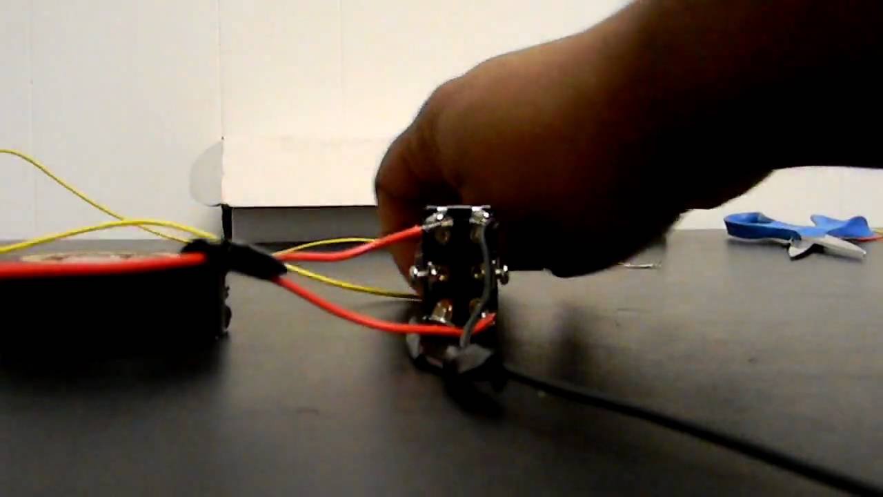
How To Wire A Linear Actuator To 3 Way Toggle Switch Youtube
Linear Actuators Thomsonlinear Com
Https Www Thomsonlinear Com Downloads Actuators Warner Electric Actuators Controls Cten Pdf
Https Encrypted Tbn0 Gstatic Com Images Q Tbn 3aand9gcqynvk5pvrcfr 2vswjrmkhmb8 Icnxzinzshs Arpwhx9hd0q8 Usqp Cau

Wiring Limit Switches On A Linear Actuator Instructables
Warner Electric Power Transmission Products
Actuator Wire Diagram Wiring Diagram For Linear Actuator Switch Wiring For Linear Actuator Electric Camber Tilt Linear Actuator Wiring Diagram Free Wiring Diagram Linear Actuator Wiring Rcs Actuator Wiring Diagram Collection External

Linear Actuator Applications Google Search Linear Actuator Actuator Mechanical Gears

Linear And Rotary Actuators Motorized Linear Slides Cylinders And Actuators Linear Actuator Linear Actuator
Source : pinterest.com
